BMS, PCS, EMS and SCADA: The Control Stack Inside a Battery Storage System
Four control layers run a battery storage system, each on its own timescale. The BMS protects the cells, the PCS moves the power, and the EMS decides what the system earns.
Published: 11 October 2026
Explainer · 5 min read
Four layers, four timescales
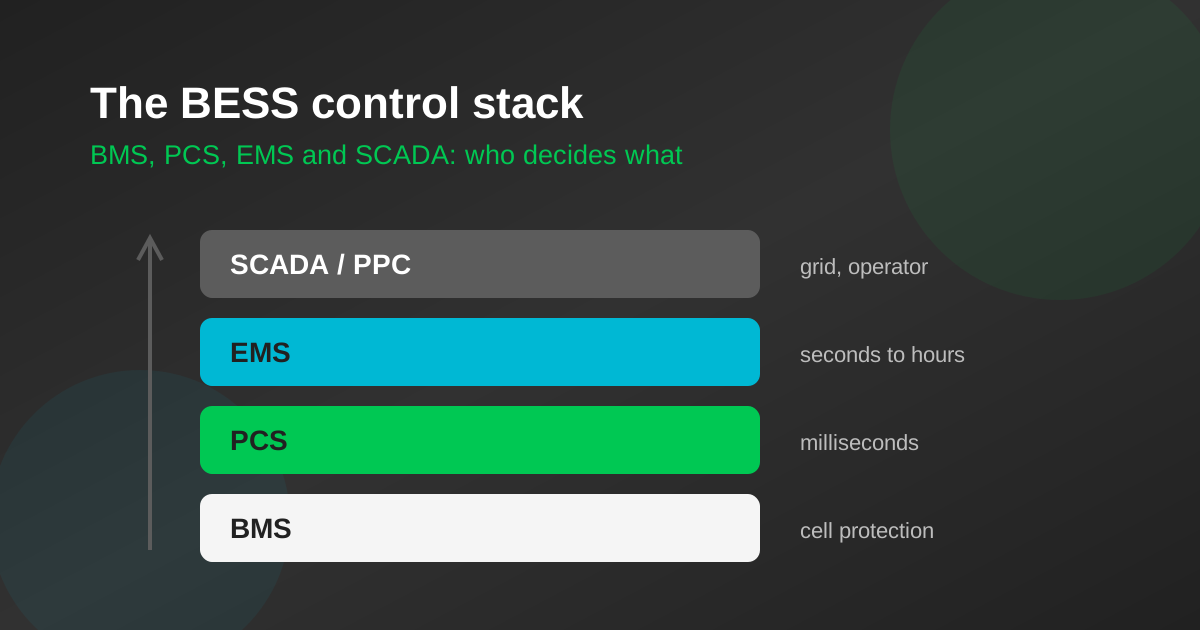
A battery storage system is run by several control systems stacked on top of one another. Their acronyms appear in every specification — BMS, PCS, EMS, SCADA, sometimes PPC — and they are often described as if they were interchangeable. They are not. Each answers a different question, on a different timescale, and the boundaries between them decide who is responsible when something goes wrong.
The simplest way to keep them straight is by speed. The lower a layer sits, the faster it acts and the less it knows about the outside world. The higher it sits, the slower it acts and the more it knows about prices, tariffs and the grid.
The BMS: protecting the cells
The battery management system lives closest to the chemistry. It measures every cell’s voltage and temperature, and the current through each string, many times a second. From those readings it estimates state of charge and state of health, runs cell balancing, and opens the contactors if anything goes outside safe limits.
Crucially, the BMS does not decide when to charge or discharge. It publishes limits: the maximum current the battery can accept or deliver right now, given its temperature and state of charge. Everything above it must respect those limits. If they are ignored, the BMS protects the cells by disconnecting them, which is safe but abrupt.
Inside a rack, the BMS typically talks over CAN bus, a robust, low-level protocol borrowed from the automotive world. Rack controllers then report upwards to a system-level BMS.
The PCS: moving the power
The power conversion system is the inverter. Its job is to make current flow in the direction and quantity it has been told to, within microseconds to milliseconds, while keeping the output synchronised with the grid and staying connected through voltage and frequency disturbances.
The PCS has its own fast protection, its own ride-through behaviour defined by the grid connection rules, and its own idea of what it can safely do. What it does not have is an opinion about whether discharging now is a good idea commercially. It receives a setpoint for active and reactive power and delivers it, clipped to whatever the BMS currently allows.
The EMS: deciding what to do
The energy management system is where the decisions are made. It reads the site meter, the tariff, the solar forecast if there is one, and the battery’s state of charge, and on a timescale of seconds to minutes it issues setpoints to the PCS. Over hours it plans a schedule: charge in these off-peak blocks, hold a reserve for backup, discharge when demand crosses this ceiling.
For a factory doing peak shaving, the EMS is watching the incoming load and must react before the fifteen-minute demand window has averaged a spike into the bill. For a grid-scale plant it is juggling the revenue streams described in how grid storage makes money, and honouring whatever availability it has committed.
The EMS decides the savings. Two systems with the same cells and the same inverter can return very different money depending on how well the EMS forecasts load, sets its demand ceiling, manages reserve and avoids needless cycling. When comparing proposals, ask to see the control strategy, not just the hardware list.
SCADA and the plant controller: facing the grid
Above the EMS sit two functions that larger plants separate and smaller sites often combine. SCADA — supervisory control and data acquisition — is the operator view: alarms, trends, logs and manual commands. The power plant controller (PPC) regulates active power, reactive power and voltage at the point of connection, so that the plant as a whole behaves as the grid operator requires, even though it is built from dozens of individual inverters.
A utility-scale plant in India will receive dispatch instructions from the relevant load despatch centre and report telemetry back to it. A C&I system behind a factory meter usually has no such link, and its SCADA may be little more than a web dashboard.
How the layers talk, and who else might listen
- •CAN bus inside battery racks, between cell monitoring boards and rack controllers.
- •Modbus, usually over TCP/IP, between the BMS, PCS and EMS. It is simple and universal, and it has no built-in authentication.
- •IEC 61850 and IEC 60870-5-104 for substation equipment and the link to grid operators, where structured data models and time-stamped events matter.
- •Hardwired signals for anything safety-critical, such as emergency stops and fire-system trips, so that protection does not depend on a network being up.
Integration between these layers is where commissioning time goes. A BMS from one maker, a PCS from another and an EMS from a third must agree on register maps, scaling, update rates and what happens when a message stops arriving. Mismatches show up as a system that works on the bench and trips in the field.
Cybersecurity follows from this. A storage system is a controllable load and generator connected to the grid. Anyone who can send it setpoints can make it misbehave, and the common protocols at the lower levels were designed for closed networks, not the internet.
- •Segment the control network from the office network and the internet
- •Route vendor remote access through a single, logged gateway with multi-factor authentication
- •Change default passwords on every controller, HMI and router at commissioning
- •Agree how firmware and software updates are signed, tested and applied
- •Keep safety trips hardwired so a compromised network cannot disable them
Indian power-sector regulators have issued cyber security requirements for grid-connected assets, and larger plants will have specific obligations. Smaller C&I sites should still apply the basics above.
What this means for a buyer
Ask who supplies each layer, and who is accountable for making them work together. A single integrator responsible for BMS, PCS and EMS integration is easier to hold to a performance guarantee than three suppliers pointing at one another. Ask to see the EMS logic for your use case in plain terms, how it handles a forecast that turns out wrong, and what data you will be able to see and export. The cells set the ceiling on what a system can do; the control stack decides how close to that ceiling it gets.
Terms in this article
Frequently asked questions
What is the difference between a BMS and an EMS?+
The battery management system (BMS) monitors cell voltages and temperatures, estimates state of charge and protects the cells by setting current limits and disconnecting if needed. The energy management system (EMS) decides when the battery should charge or discharge, based on load, tariffs and forecasts. The BMS sets limits; the EMS makes decisions within them.
What does the PCS do in a battery storage system?+
The power conversion system is the bidirectional inverter that converts between the battery’s direct current and the grid’s alternating current. It delivers the power setpoints it receives from the EMS within milliseconds, stays synchronised with the grid and rides through disturbances, while respecting the limits published by the BMS.
Why does the EMS matter so much for savings?+
Two systems with identical cells and inverters can earn very different amounts depending on how well the EMS forecasts load, sets demand ceilings, manages reserve and avoids unnecessary cycling. The hardware sets what is possible; the control strategy decides how much of it is captured.
Want this applied to your own numbers?
Every solution page carries a calculator that shows its own arithmetic — storage savings, lithium against lead-acid, and home pack sizing.